3013: Difference between revisions
Jump to navigation
Jump to search
(created the page) |
(added pictures of the card) |
||
| Line 1: | Line 1: | ||
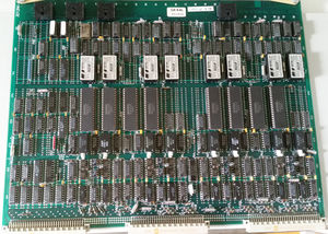
[[File:3013 component.jpg|thumbnail|3013, 8 terminal interface, component side]] | |||
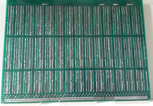
[[File:3013 solder.jpg|thumbnail|3013, 8 terminal interface, solder side]] | |||
[[File:3013 card edge.jpg|thumbnail|3013, 8 terminal interface, card edge]] | |||
'''3013''' is the 8 terminal interface board. A card with interfaces for 8 serial connected [[terminal|terminals]], using [[RS-232]] or [[current loop]] interface. | '''3013''' is the 8 terminal interface board. A card with interfaces for 8 serial connected [[terminal|terminals]], using [[RS-232]] or [[current loop]] interface. | ||
{{Stub}} | {{Stub}} | ||
Revision as of 13:53, 14 July 2016
3013 is the 8 terminal interface board. A card with interfaces for 8 serial connected terminals, using RS-232 or current loop interface.
|
|
This article is a stub. You can improve NDWiki by expanding it. |
Introduction
Switches and indicators
The following switches and indicators are on the card
Location 21J - baud-rate selector, group A
Location  9J - baud-rate selector, group B
Location  6J - device-number selector, group B
Location  3J - device-number selector, group A
The baud rate switches sets the initial speed setting for each interface group. Baud rate switch settings
- 0 - 110 baud
- 1 - 150 baud
- 2 - 300 baud
- 3 - 2400 baud
- 4 - 1200 baud
- 5 - 1800 baud
- 6 - 4800 baud
- 7 - 9600 baud
- 8 - 2400 baud
- 9 - 600 baud
- 10 - 200 baud
- 11 - 134.5 baud
- 12 - 75 baud
- 13 - 50 baud
Setting 14 and 15 is not used. In addition there is one switch for each interface that selects the mode of the interface:
- switch set to 0: current loop
- switch set to 1: RS232-C (V24)
References
Norsk Data Document ND–06.026.01 ND-110 Functional Description

