NORD-1 Serial 47
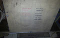
NORD-1 Serial number 47 was given to me by Fagskolen Innlandet in Gjøvik, Norway in the summer of 2016. I think it's been at the school for all of it's life since the only inventory labels on it is from the school. The only documentation surviving is the lists of cards on the inside of the front door. They give a date of summer 1972 as the build date.

There is an article about a couple of machines delivered to NTNU in ND NYTT 5 September 1972. This is one of them.[1]
I'm currently looking for:
- Missing cards : 160, 113, 185
- Information and drawings of the following cards :
- Software, printed or on tape. Especially looking for TSS, Fortran or MAC
- Peripherals, card punch, card reader, tape reader, tape punch, drum memory... and anything else that was used with the NORD-1.
- Manuals (will be scanned and shared)
If you can help with any of it, please contact me, Gandalf.
Configuration
The system is equipped with
- 32 kword of core memory
- 9 TTY interfaces
- A cartridge disk interface
- An I/O channel (connectors I/O channel data in, I/O channel data out, I/O channel control)
- Asynchronous modem
- Centronics printer interface
- Facit punch 4070 interface
- Digitronics tape reader interface
Missing parts and damages
Some cards seems to be missing and minor damages
Shelf D :
* Missing cards on position 26 and 27.
 -- 26 : 160 Punch buffer
   There are several cards of this type in the machine, so no problem to reproduce.
 -- 27 : 113 I Card reader contr.
   I have no drawings or extra cards of this one, can be hard to reproduce.
Shelf E :
* Missing card on position 20.
 -- 20 : 195 Duplex start stop buffer for TTY 6
   There are several cards of this type in the machine, so no problem to reproduce.
Shelf F :
* Missing cards on position 24, 25 and 26.
 -- 185 Data buffer
 There is a drawing of this one so it should be possible to build some new cards.
Some switches are broken on the front panel.
Card cage configuration
It seems that the configuration of a CPU is more or less individual, depending on which options have been ordered. In my copy of Norsk Data Document ND–01.004 NORD-1 HARDWARE MANUAL there are two different CPU:s described, no. 29 and no. 35. The no. 47 cpu is closest to the no. 29 CPU but not exactly the same.
Shelf C
- pos 1 : 151 Time counter snr 103
- pos 2 : 128 Protect control snr 78
- pos 3 : 141 Protect reg. snr 62
- pos 4 : 132 Interrupt control snr 97
- pos 5 : 106.1 Interrupt register snr 109
- pos 6 : 106.2 Interrupt register snr 213
- pos 7 : 140.2 Lamp register snr 180
- pos 8 : 140.1 Lamp register snr 182
- pos 9 : 150 Register snr 131
- pos 10 : 108.4 Register snr 351
- pos 11 : 102.4 Register snr 379
- pos 12 : 103.4 Arithmetic snr 362
- pos 13 : 101.4 Bus memory snr 391
- pos 14 : 108.3 snr 111
- pos 15 : 102.3 snr 380
- pos 16 : 103.3 snr 361
- pos 17 : 101.3 snr 392
- pos 18 : 108.2 snr 350
- pos 19 : 102.2 snr 387
- pos 20 : 103.2 snr 389
- pos 21 : 101.2 snr 390
- pos 22 : 108.1 snr 345
- pos 23 : 102.1 snr 388
- pos 24 : 103.1 snr 390
- pos 25 : 101.1 snr 142
- pos 26 : 158/II Memory buffer snr 309 4 x 6 7 12 15
- pos 27 : 158/II snr 327 3 x 4 5 12 13
- pos 28 : 158/II snr 318 2 x 2 3 10 11
- pos 29 : 158/II snr 312 1 x 0 1 8 9
- pos 30 : 159 Memory OR snr 86
- pos 31 : 169 Cambridge control snr 97
- pos 32 : 110 Panel buffer snr 109
Shelf D
- pos 1 : 125 Shift counter snr 94
- pos 2 : 123 Cycle counter snr 104
- pos 3 : 124 Counter control snr 119
- pos 4 : 127 Control flip-flops snr 106
- pos 5 : 131 Addressing control snr 96
- pos 6 : 90N40.2 NORD 90 Glue logic
- pos 7 : 90N40.1
- pos 8 : 109 Register control snr 101
- pos 9 : 130 Addressing control snr 107
- pos 10 : 115 Arithmetic control snr 106
- pos 11 : 126 Shift control snr 95
- pos 12 : 134 Floating control snr 96
- pos 13 : 135 Floating control snr 94
- pos 14 : 136 Floating control snr 92
- pos 15 : 137 Floating control snr 97
- pos 16 : 146 Register transfer snr 81
- pos 17 : 133 Bit instruction snr 101
- pos 18 : 122 Assembler snr 108
- pos 19 : 120/II I/O Control snr 105
- pos 20 : 163/II I/O Output and clock snr 53
- pos 21 : 166 I/O Output snr 82
- pos 22 : 166 I/O Output snr 81
- pos 23 : 165 I/O Input snr 67
- pos 24 : 165 I/O Input snr 70
- pos 25 : 301 DP Reader Buffer
- pos 26 : 160.I Reader/punch contr. (missing)
- pos 27 : 113 I Card reader contr. (duplex) (missing)
- pos 28 : 179 Punch buffer snr 103
- pos 29 : 160 Simplex control snr 155 TTY
- pos 30 : 195 Duplex Start-stop buffer snr 4
- pos 31 : 190.1 Cable card snr 30
- pos 32 : 504/II Cable card Bus receiver snr 8
Shelf E
- pos 1-7 : Not used
- pos 8 : 196 GH 1101-J Control snr 22
- pos 9 : 170 Duplex buffer snr 291 (Marked Modem with on a sticker)
- pos 10 : 160/II Simplex control snr 668
- pos 11 : 302 Centronics buffer snr 33
- pos 12 : 160/II Simplex control snr 683
- pos 13 : 90N08 NORD 90 glue logic
- pos 14 : 195,9 Duplex start-stop buffer snr 3
- pos 15 : 160/II snr 433 TTY 9,IN 142 OUT 143
- pos 16 : 195,8 snr 36
- pos 17 : 160/II snr 418 TTY 8,IN 140 OUT 141
- pos 18 : 195,7 snr 43
- pos 19 : 160/II snr 421 TTY 7,IN 136 OUT 137
- pos 20 : 195,6 snr --- A 160/II card snr 622 were put here, moved to pos D26
- pos 21 : 160/II snr 419 TTY 6,IN 126 OUT 127
- pos 22 : 195,5 snr 38
- pos 23 : 160/II snr 435 TTY 5,IN 124 OUT 125
- pos 24 : 195,4 snr 37
- pos 25 : 160/II snr 420 TTY 4,IN 122 OUT 123
- pos 26 : 195,3 snr 42
- pos 27 : 160/II snr 436 TTY 3,IN 120 OUT 121
- pos 28 : 195,2 snr 41
- pos 29 : 160/II snr 397 TTY 2,IN 104 OUT 105
- pos 30 : 90X08 Buffer card
- pos 31 : 189 Cable card snr 13
- pos 32 : 7316 Expander
Shelf F
- pos 1-13 : Not used
- pos 14 : 313/II Cartridge control snr 12
- pos 15 : 312 Cartridge sequence snr 7
- pos 16 : 311 Cartridge timing snr 4
- pos 17 : 310 Cartridge disc receiver snr 9
- pos 18 : 309 Cartridge disc transmit snr 10
- pos 19 : 182 Cartridge disc d.c. register snr 39
- pos 20 : 183/II Cartridge disc d.c. counter snr 36
- pos 21 : 180/III Cartridge disc dev, instructions snr 22
- pos 22 : 181/II,1 Cartridge disc 7/8 register snr 74
- pos 23 : 181/II,2 Cartridge disc 7/8 register snr 82
- pos 24 : 185,9 Data ch. M control (missing)
- pos 25 : 185,8 Data ch. M data in (missing)
- pos 26 : 185,7 Data ch. M data out (missing)
- pos 27 : 165,4 Multiplexer, addresses snr 151
- pos 28 : 165,3 Multiplexer, addresses snr 168
- pos 29 : 165,2 Multiplexer, data snr 142
- pos 30 : 165,1 Multiplexer, data snr 169
- pos 31 : 305 Memory control snr 10
- pos 32 : 503/II Data ch. driver snr 39
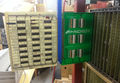
Core memory

The core memory was made by Cambridge Memories INC, Newton, Massachusetts or CMI, the model name is EXPANDACORE 18. The memory have two or four channels in to it so it is possible to build a multi CPU machine by connecting two (or maybe more) to the same memory to pass messages between them. The core memory is built up from modules. One rack can hold four controllers and eight memory planes of 4 kword each. It looks like the original configuration only came with 24 kword but later on two additional memory planes were added.
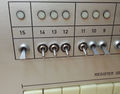
Operators panel
Directly above the CPU card crate is the Operators panel. It has several keys for controlling the execution of programs and examination of registers and memory.
There are two different lamps in the panel and these burns out sometimes.
- 6V 40 mA T1-3/4 midget flange bulb, used in back lit buttons
- 5V 60 mA T1 sub midget flange bulb, used in bit indicators.
Some buttons isn't lit up and doesn't need lamps. Unlit lamps are "MASTER CLEAR", "SINGLE INSTR", "SET ADDRESS" and "DEPOSIT".
A lot of the switches are bad and is needing replacement. NOS from eBay, 5 switches is ordered.
The operators panel is connected to the 110 Panel buffer which buffers the key presses and two 140 Lamp register cards. The lamp register selects what to show at the bit indicators.
Price
The prices are from an information sheet from a fair. Exactly which year it was isn't easy to know but probably quite early.
- NORD-1 CPU 205.000 NOK
- 16K x 18 bit core memory, 1.5 ms 180.000 NOK
- Teletype ASR33 14.000 NOK
- Tape reader 15.000 NOK
- Tape punch 15.000 NOK
- Card reader 30.000 NOK
Based on these price tag on this system was 879.000 NOK, quite a lot of money in it's time.
Current status
The system resides in the ND-Collection in Umeå. It is not operational yet but there is good hope that I will be able to restore it to running status.
- 2016-07-08
- All the cards were pulled out and then power were applied and the lights went out in the workshop.
- The RF-filters on the power inlet trips the RCD with too much ground current, probably by capacitive loading. The filter were bypassed by two wires.
- Power were applied again and the voltages of the power supplies were checked. The main bus held 5.05V on the bus bar.
- All the CPU-cards were inserted and the resistance of the 5V bus were measured, 0.1 ohm... the resistance welt up to 8.6 ohm when a card (pos 28 shelf D) were pulled out.
- A faulty capacitor was located and removed
- 2016-07-11
- Back with the master key, now I could start the system. It turns out that the right relay controls the power to the two lower 5V power supplies which delivers power to the CPU and I/O racks in the front. The left relay controls the power to the upper power supplies which delivers power to the core memory. The dials on the relays is a time delay switch from 0 to 20 seconds delay so the power up and down sequence can be controlled.
- When the front panel was enabled I could turn the power on and use stop, continue and single step to get a response from the CPU. Bit 4 is dark and bit 9 a bit dim, but other than that the lamps are working. I don't seem able to switch the source for the indicators though.
- The core memory is on power too and still no magic smoke!

- 2016-07-13
- Operators panel, disassembled to getting at the broken switches. When I have it on the bench I checked he lamps too and discovered there were a lot missing from the back lit keys. D4 and D9 has been acting up, and D4 had a broken lamp. New lamps and a stash for coming years were ordered on eBay.
- The broken switches were removed and documented. I didn't have or couldn't locate any drop-in spares so I have decided to put some of my second hand switches that I had laying around. The job will be finished in a couple of days.
- 2016-07-13
- Replaced the switches with another model. All the switches are working now but the machine seems a bit random. Even at stop the lamps can flutter and change. I need a NORD-1 extender card or two so I can start debugging the logic cards.

- 2016-07-18
- New lamps have arrived and I discovered that there are two different types. With a flange or with a groove. What I got was groove but I needed flange. At least that was a simple problem to fix, just solder a suitable thick copper wire into the groove and I could use them.
- New lamps have arrived and I discovered that there are two different types. With a flange or with a groove. What I got was groove but I needed flange. At least that was a simple problem to fix, just solder a suitable thick copper wire into the groove and I could use them.
With the lamps working I could finally see that I was able to enter a value into some of the registers. The front panel still lights all the register lamps except for F, that is black all the time. Time to do some reverse engineering on the operators panel.
- Found some broken switches, H is totally broken, "LOAD" glitches but will remain as is since it has feedback and isn't used that often. New switches are ordered, NOS.
- 2016-07-22
- The operators panel is reverse engineered to 90%, enough to realize that any floating key will be seen as a pressed key. That means that the broken H-key froze the panel. With the sensing cable soldered to ground the panel started to work again... although a bit erratic because there are more keys with high resistance.
- I can now deposit values into the R-register and I can watch the other registers, but what happens after that seems to be nothing. I'm suspecting that I'm not reading or writing to the core memory.
- 2016-07-25

- To be able to measure on cards I need an extender card... so I designed one and combined it with a prototyping card. This way I can rebuild some of the missing cards. The minimum quantity to order was five, so better combine some functions. The card is already ordered and will be here in a week or two.
- 2016-08-04
- The extender cards arrived, looking great! Time to order components.
- 2016-08-09
- Finally finished soldering the extender card. Had to do a measurement so I plugged it in 151 TIME COUNTER, the CPU clock and sequencer. It worked great! Verified that the MASTER CLEAR signal arrived at the card and looked okay.

- 2016-08-19
- Not much have been done on the NORD-1 over the past weeks, work got in the way. Some small progress have been done though, all the lamps is now working. I've spent some time on reading schematics, but poor copies makes it hard to find signals as they go in and out of cards. I also have done some measurements on cards and signals and it looks okay. The operators panel is a bit sensitive though.
Plans
The system will be put in working order some time in the future. First it will be documented.
Gallery
-
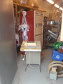
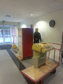 Picking up a NORD-1 in Gjövik.
 -
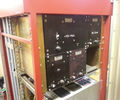
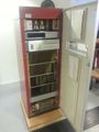 The front door opened.
 -
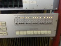
 Front panel with broken switches.
 -
 Logo in cast aluminum.
 -
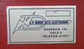 Serial number plate.
 -
 Early logo before the name change to Norsk Data AS.
 -
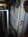
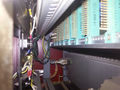
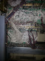 Wiring loom at the back of shelf E and F.
 -
 Top of core memory, thin core wires behind the resistors.
 -
 Finally at home after a 1000 km journey.
 -
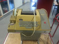 ASR33 terminal that came with the machine.
 -
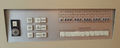
 Connectors with name plate.
 -
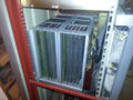 The core memory rack.
 -
 Wiring loom back of the CPU, shelf C and D.
 -
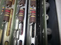
 Front of small power supplies.
 -
 Back of small power supplies.
 -
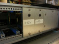
 Main power supplies.
 -
 Power on for the first time in a long time.
 -
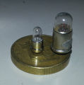 Light bulbs from the Operators panel
 -
 Replaced switches but of wrong model.
 -
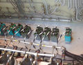 Backside of the replaced switches.
 -
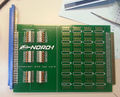
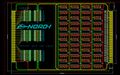 The design for the new extender card.
 -
 The design for the new extender card.
 -
 The design for the new extender card.


